
Optimize Designs Across Technologies
– Without Getting Lost in the Process
![]()
GTS Cell Designer is a tool suite for planning and implementing advanced DTCO workflows – combining layout-based structure generation incorporating detailed technology information (accounting for variability) and advanced physical device and circuit simulation in a parametrized and customizable environment.
The Smarter Approach to Design-Technology Co-Optimization
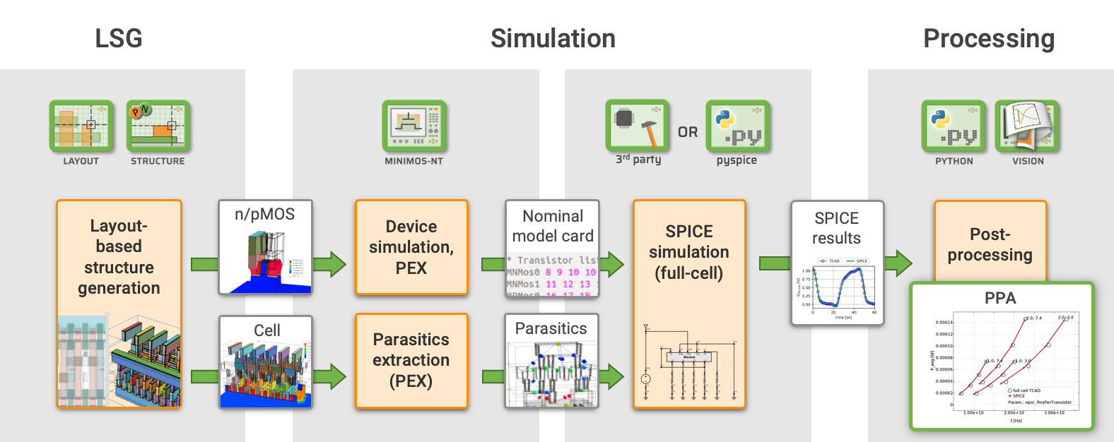
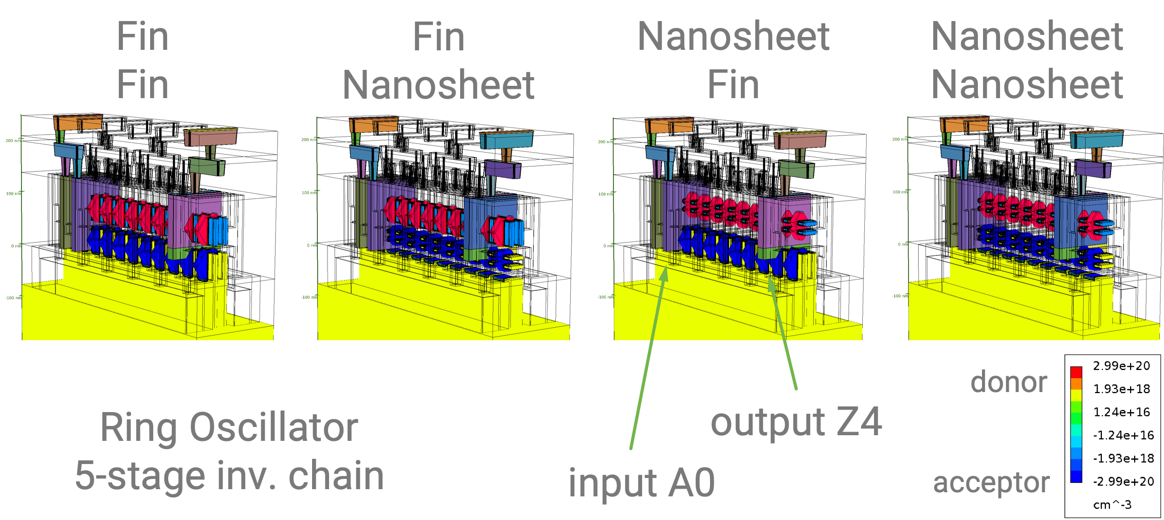
Deciding on a technology has big implications from device and cell to circuit and system level. With GTS Cell Designer you can benchmark your technology options (FinFET, NWFET, NSFET, CFET, VFET and more) and get the best design for each. Use the device parameters calculated by GTS Nano Device Simulator (NDS) combined with technology information to obtain an accurate 3D TCAD model of your logic cell. With the automated Spice Model Extractor and the field-solver based parasitics extraction (PEX) you will obtain an accurate circuit representation from a fully consistent TCAD flow. Study cell and device variability, calculate parasitics, power-performance-area (PPA), and gain insight on variability and reliability of the circuits. Optimizations can be run for various aspects – see Cell/Circuit Optimization.
- Power, Performance, Area (PPA)
- Parasitics
- Thermal robustness
- Reliability, time-to-failure
- Variability, process variations
Focus on Your Application
Explore key technology parameters which you get from your Cell Designer DTCO workflows. No need for hard-to-obtain process data, no need to dig into process details but focus on achieving your application target
Built on Experience, Matured with Industry Feedback
Based on its scientific and practical expertise in device simulation, as well as feedback from customers, GTS has prepared example workflows matching the needs of the semiconductor industry. In contrast to conventional, process-related solutions, the required amount of input data for a full-fledged DTCO workflow is moderate and well obtainable – a key aspect when working with contractors. GTS Cell Designer satisfies the demands for reasonable turn-around execution time, and features automatic extraction of key technology parameters as results. With all tools originating from one source, sharing interfaces and data structures, GTS is delivering a consistent solution which is easy-to-use yet powerful and customizable.
For Verification – Full TCAD DTCO
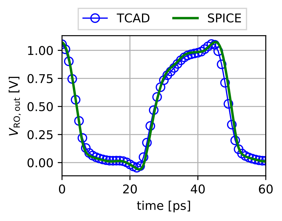
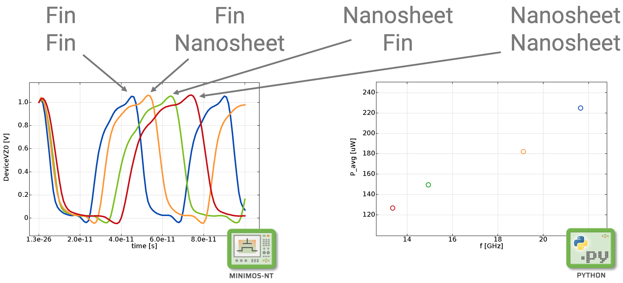
With the GTS Spice Model Extractor and the GTS Parasitics Extraction as part of the Cell Designer DTCO flow, a completely consistent TCAD-based characterization of the standard cell becomes possible for the first time. Some might say you should never go full TCAD, but with that in mind, the results can be easily verified by running our full TCAD DTCO flow with only four tools in the chain. As shown here, the calculated transients from the TCAD and Spice approach are in excellent agreement giving credit to our fast but accurate Spice DTCO flow.
As Cell Designer user you can always verify your results.
Modular, yet Compact – a Comprehensive Solution
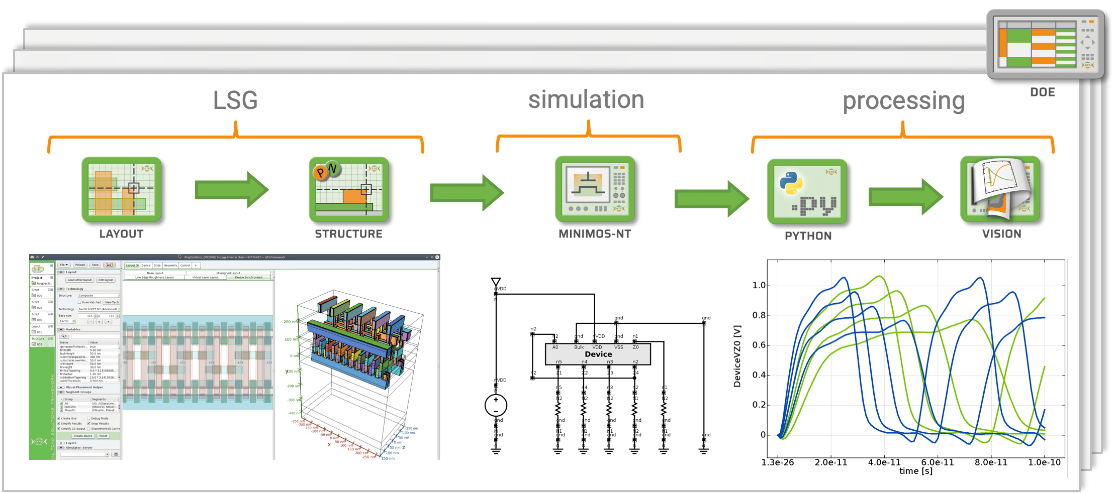
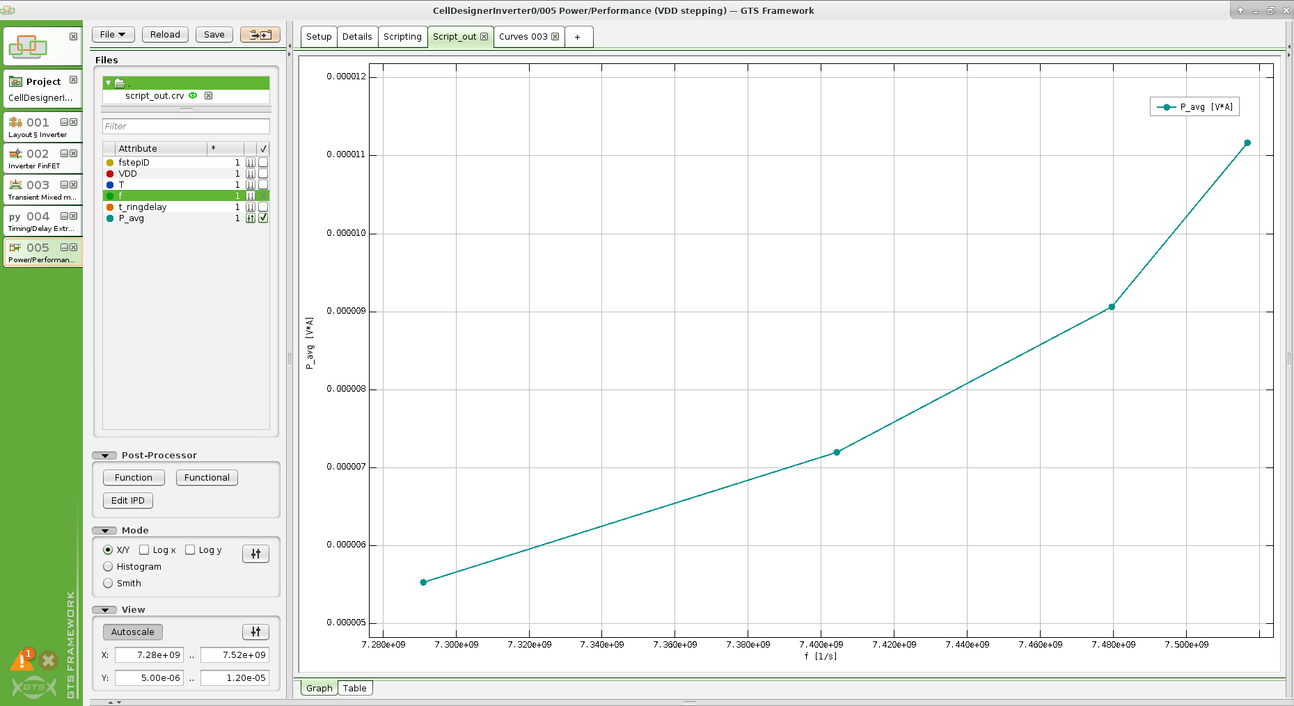
GTS Cell Designer is more than just a combination of individual tools. While each step of the workflow is executed in a separate simulation tool (e.g. Structure, Minimos-NT, VSP) or data processing tool, the workflow (scheduling, distributed execution, post-processing, visualization) is an automated, integrated process in GTS Framework / Cell Designer.
Features
- Parameterized layout templates as well as a GDSII layout editor
- Fast and reliable 3D structure generation, including doping and meshing, fully configurable
- Full 3D transient mixed-mode device simulation
- Variability, reliability for aging-aware DTCO
- Spice Model Extractor: fully automated and scriptable generation of BSIM model cards
- Resistance and capacitance extraction of FEOL, MOL and BEOL in one go
- Netlist generation
- Spice simulation for PPA extraction using internal Python based solution or 3rd Party solver
- Data-analysis and post-processing using flexible Python modules
Tutorials and Application Examples
Next to the published papers, GTS provides typical DTCO workflows as reference and starting point – see Tutorials and Application Examples.

")
")
")


GTS Cell Designer alleviates the major issues faced by conventional DTCO approaches. Cell Designer generates realistic but simulation-ready cell geometries without the need for hard-to-obtain process details. You get improved turn-around times and a solid, physically sound base for model calibration. Cell Designer integrates the flow in one familiar user interface, providing automated Spice model and parasitics extraction while still allowing for full customization by DOE/splits, parameters, scripting, etc. Application examples and tutorials ensure a quick start.